

A fixture designed around one motor component may be asked to handle another part number later. The second part can sit closer to the displacement sensor even though the fixture locates correctly and the bracket has never moved. Before approving a sensor for several variants, work out how far the actual measurement surface can move. The nominal fixture height is only one input.
Write the nearest and farthest positions down
For each part, measure or calculate the closest and farthest position of the feature relative to the measurement reference specified for the proposed sensor. Include part tolerances, seating variation and any fixture motion present when a reading is taken. If two sources of movement can occur together, include that combination. A feature shown at its nominal height on two drawings may have a different operating envelope on each variant.
Use distances along the sensor’s measuring axis. A position envelope on paper can still hide a practical problem. A taller nearby rib may enter the beam after a changeover, or the point on the part that the sensor sees may shift. Identify the feature on the fixture drawing so all variants are evaluated against the same measurement task.
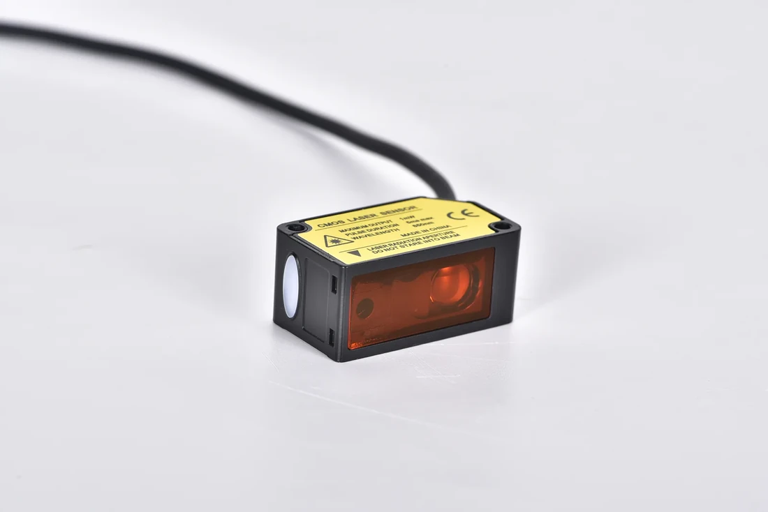
LK-F laser displacement sensor front and side view
Compare the envelope with a model s actual window
The LK-F reference distances and measuring windows include a 30 mm reference-distance option with a stated measuring range of plus or minus 5 mm. That gives a nominal interval of 25 to 35 mm. In a hypothetical fixture with target positions from 26 to 33 mm, the available measuring margin is 1 mm at the near end and 2 mm at the far end. A later variant that can sit at 24 mm would fall outside the same nominal window.
The arithmetic screens the geometry. Proving that the fixture can distinguish accepted parts from rejects takes measurements on representative parts, at the intended angles and with the chosen settings. Published repeatability and the reject limit are separate numbers. Keep the exact model and its test conditions with the comparison so that an appealing specification from one version is never carried over to another.
Decide whether to move the bracket or change the sensor
If one end has too little travel left, moving the bracket may work when the opposite end has room. Draw both ends of the envelope again after the move, then check the beam’s spot, nearby features and access for changeovers. If the whole part family needs a larger interval, use the comparison of laser displacement sensor families to shortlist alternatives by window and output.
Keep the approved near and far positions on the fixture setup sheet. A new part number can then be reviewed against a defined physical envelope before its controller settings are copied from the previous run.
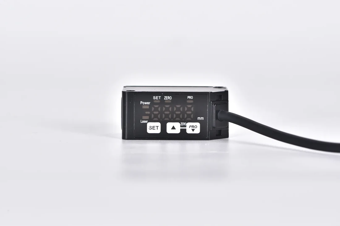
LK-F display and control keys
